If you’ve ever sourced aluminum die casting parts, you know that a well-designed mold doesn’t just produce a good part—it cuts costs, shortens lead times, and eliminates headaches down the production line. As an aluminum die casting parts supplier with over a decade of working with automotive, electronics, and industrial equipment clients, I’ve seen too many projects derail because of a mold design that seemed solid on paper but failed in practice. Today, I want to share the practical, science-backed strategies we use to optimize mold designs for aluminum die casting—strategies that turn a good mold into a great one, and keep production running smoothly. Aluminum Die Casting Partsr
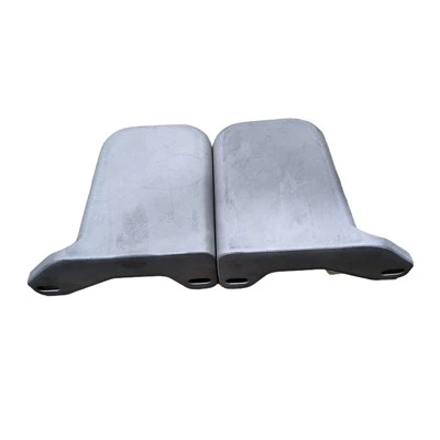
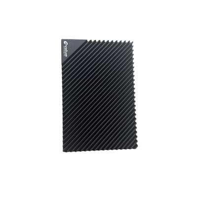
First, let’s ground this in the basics that many designers skip at their peril: aluminum’s unique material properties. Unlike plastic, aluminum has high thermal conductivity, a narrow solidification range (it goes from fully liquid to fully solid very quickly), and a tendency to shrink as it cools. If you ignore these, you’ll end up with parts that have porosity, warpage, or dimensional inconsistencies. Early in our work with a large automotive electronics client two years ago, their original mold design had a single gating point at the center of a complex heat sink component. The aluminum cooled too fast at the edges, creating cold shuts—gaps where the metal never fully fused. We revised the gating based on aluminum’s flow dynamics, adding two side gates to ensure uniform fill, and cut the defect rate from 18% to less than 2% almost overnight. That’s not magic; it’s designing for the material, not just spec sheets.
Next, gating and runner system design—this is the backbone of mold optimization, and it’s where most half-baked designs go wrong. The goal here is simple: get molten aluminum into every corner of the mold cavity fast enough to avoid cold shuts, but slow enough to prevent turbulence that traps air (the number one cause of internal porosity in die casting). Our team uses a rule we’ve refined over hundreds of projects: the runner system should be sized to maintain a consistent metal velocity of 30 to 60 meters per second, depending on part thickness. For thin-wall parts (under 2mm), we lean toward the higher end of that range to make sure the metal fills before it solidifies. For thicker parts, we use lower velocity and add venting channels to let trapped air escape. We also always design gates to be as small as possible while still allowing full fill, because smaller gates reduce the amount of secondary machining needed later. A medical device client came to us last year with a complex surgical instrument bracket that required post-casting grinding because their existing gate was too large. We revised the gate to be flush with the part’s surface, eliminating 90% of that grinding step and cutting their per-part processing time by 12 seconds. Small changes, big impacts.
Then there’s venting—something that’s often an afterthought in mold design, but is critical for high-quality aluminum castings. When molten aluminum is injected into the die cavity, it pushes air and even residual lubricant fumes out. If those gasses can’t escape, they get trapped as bubbles in the part, leading to weak spots or surface defects. For most parts, we design vent slots 0.02 to 0.05mm deep at the edge of the cavity, opposite the gating system. For very intricate parts with tight internal spaces, we use porous metal inserts in the mold to pull out trapped air through the die itself, no extra slots needed. I remember a lighting fixture client a few years back who was getting 25% of parts rejected for surface blisters, a defect caused by trapped gas under the finish layer. We added porous vent inserts to the mold and adjusted the vent slots, and the reject rate dropped to less than 1%. It’s a simple fix, but it requires thinking about every nook and cranny of the cavity before the mold goes into production.
Cooling system design is another area where optimization pays off big time. Aluminum cools much faster than many other metals, so the mold’s cooling channels need to be designed to balance heat removal across the entire part, preventing uneven solidification which leads to warpage. Uniform cooling also reduces cycle time—every minute shaved off a die casting cycle adds up to thousands of parts per month. For simple, thick parts, we use straight drilled cooling channels parallel to the part’s main surfaces. For complex, contoured parts (like the heat sinks we worked on earlier), we use conformal cooling channels—channels that follow the exact shape of the part, instead of straight lines. A power tool manufacturer we work with switched to conformal cooling in their motor housing mold, cutting cycle time from 45 seconds to 28 seconds, a 38% reduction. The key here is to calculate heat transfer across the part using software (we use MagmaSoft for our simulations) and adjust channel diameter and spacing to match. For areas that hold more heat (like thick ribs or bosses), we place cooling channels closer together to pull that extra heat out faster.
Draft angles and ejection systems are often overlooked, but they prevent the most common post-casting headache: parts that stick in the mold, leading to damage and downtime. Aluminum expands when heated, so when it cools and solidifies, it shrinks around the mold cores and cavities. If draft angles are too small, the part will stick; if they’re too large, you end up with extra material that needs machining. For most aluminum die casting parts, we use a minimum draft angle of 0.5 degrees for external surfaces and 1 degree for internal cores, though we adjust for part thickness and complexity. For deep cores, we add lifters or slide mechanisms to the mold, which carefully pull the part away from the core without scratching it. Last year, a client making custom camera housings was seeing 10% of parts damaged during ejection because their mold’s draft angles were only 0.25 degrees. We adjusted the draft and added a hydraulic ejection pin system, cutting damage to less than 0.5%. It’s a small adjustment, but it prevents hours of downtime per week.
Parting line location is another critical optimization that impacts both part quality and secondary operations. The parting line is where the two halves of the mold meet, and it’s often the source of flash (extra aluminum that seeps out between the two halves) and requires trimming later. We always locate the parting line on the least visible surface of the part, especially for parts that will be finished with paint or anodizing. For example, on a consumer electronics case, we place the parting line along the bottom edge or inside a seam that will be hidden when assembled, instead of along the front or top surface that’s seen by the end user. This eliminates the need for extensive grinding or polishing to hide parting line marks, saving time and cost. We also avoid placing the parting line across thin features (like fins on a heat sink) because this can break or bend during trimming. Instead, we shift the line to a solid section where it’s easier to machine.
Finally, prototype testing and simulation—this is where we catch flaws before they become expensive mistakes. We don’t just design a mold and send it to production; we use computer-aided engineering (CAE) software to simulate the entire die casting process: metal fill, solidification, shrinkage, and stress. This lets us spot potential issues like cold shuts, porosity, or warpage before the mold is even machined. For complex parts, we also make a small prototype mold to test with actual aluminum before committing to a full production mold. A construction equipment client came to us with a large bracket that was failing fatigue tests because of internal porosity. Our simulation flagged a high-stress area where porosity was likely to form, and we adjusted the mold’s gating and venting to reduce porosity in that exact spot. The prototype passed fatigue testing, and the production mold has been running with near-zero defects since it launched. Even with all our experience, simulations and prototypes save us from costly reworks that can set projects back weeks.
As an aluminum die casting parts supplier, our job isn’t just to deliver parts that meet specs—it’s to design molds that make production efficient and parts that are easy to finish. Every optimization we make, from gating size to cooling channels, is rooted in understanding aluminum’s properties and the real-world needs of our clients. If you’re working on a project that requires high-quality aluminum die casting parts, getting the mold right from the start will save you time, money, and frustration down the line. To discuss how we can optimize a mold for your specific parts or review an existing design, feel free to reach out to our team for a consultation.
Die Casting Parts References
- Die Casting Engineering: Aluminum Alloys and Process Design, 2nd Edition. Society of Manufacturing Engineers, 2018.
- MagmaSoft Die Casting Simulation User Guide, Version 11. Magma GmbH, 2022.
- The Aluminum Die Casting Handbook, 5th Edition. Aluminum Association, 2020.
Suzhou Ruide Die-Casting Mold Co., Ltd.
Address: No.2, Wanchen Road, Huayang Village, Wangting Town, Xiangcheng District, Suzhou City, Jiangsu Province
E-mail: jada@cnrdmj.com.cn
WebSite: https://www.cnrdmold.com/
